Standard Driver Sheets
In addition to the unique MAIN DRIVER SHEET that is available for each driver, you can create several STANDARD DRIVER SHEETS for each driver. The STANDARD DRIVER SHEETS provide additional fields, which you can use to control communication.
Note: You can have a total of 9,999 Standard Driver Sheets for all drivers in your project.
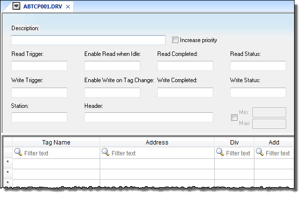
To open a STANDARD DRIVER SHEET, right-click on a driver subfolder and select Insert from the resulting popup (see the following figure).
Figure 1. Sample STANDARD DRIVER SHEET


The STANDARD DRIVER SHEET dialog is divided into two areas:
- Header area (top section), contains parameters that affect the all tags configured in the Body area of this worksheet
- Body area (bottom section), where you define the relationship between tags in the project and their field equipment address.
Use the Header area parameters as follows:
- Description field: Type a description of the STANDARD DRIVER SHEET for documentation purposes.
- Increase Priority checkbox: Click (check) to keep the reading and writing commands for this sheet on the top of the communication queue whenever they are triggered.
CAUTION:You must give special attention to this worksheet when you enable the Increase Priority option. If the worksheet keeps triggering communication commands, the project may never be able to execute the other driver sheets.
- Read Trigger field: Type a tag that triggers the project to read the worksheet automatically when you change this tag’s value.
- Enable Read when Idle field: Type a tag or constant value. Use a tag (or constant) value greater than zero, to enable reading from the equipment.
CAUTION:If you use a constant value (other than zero), be sure that your project requires a continuous reading because this value places a reading request in every communication scan.
- Read Completed field: Type in a tag and the communication driver toggles the tag when it completes a read command.
- Read Status field: Type in a tag and the communication driver updates the tag with the status of the last read command.
- Write Trigger field: Type a tag value to activate a group reading. Whenever you change this tag value, the program writes an equipment worksheet.
- Enable Write on TagChange field: Type a tag or constant value (not zero) to enable the communication driver to check the worksheet continuously for changes in the tag value. If a change occurs, the project writes this value to an address in the field equipment.
- Write Completed field: Type in a tag and the communication driver toggles the tag in this field when a write command completes.
- Write Status field: Type in a tag and the communication driver updates the tag with the status of the last write command.
- Station field: Type the equipment station number within the network. The syntax in this field varies with each communication driver. Refer to the appropriate driver’s documentation for further information.
Tip: For some drivers, if you’ve configured the driver to do serial encapsulation via TCP/IP or UDP/IP, then the station may be specified using the following format:
IP_address:port_number|station
For example:10.169.25.18:1234|Station5
To see if this feature is supported on your selected driver, refer to the driver’s documentation.
- Header field: Specify the data type and/or initial address to be read or written in the equipment. The syntax in this field varies with each communication driver. Refer to the appropriate driver’s documentation for further information.
Note: You can use text in the Station and Header fields with tag values using the text {tag} syntax.
- Min and Max checkbox (not labeled): Click (check) to specify the minimum and maximum values for field equipment data.
- Min and Max fields (become active only when you enable the Min and Max checkbox): Type a range of values to be converted into an engineering format. These fields determine the minimum and maximum range of values. These values affect all tags in the worksheet.
For example, Memory holds values from 0 to 4095, which means 0% to 100% in the user interface. So for this example, you must specify 0 to 100 for the min and max tag parameters.
Use the Body area parameters as follows:
- Tag Name field: Type a tag name for the communication driver to use.
- Address field: Type a field equipment address (or address offset) related to the project tag. The syntax in this field varies with each communication driver. Refer to the appropriate driver’s documentation for further information.
- Div field: Specify a division constant to use when scale adjustment is required. The project uses this value as a division factor in a read operation and a multiplication factor in a write operation. Do not use this field if you are already using Min or Max in the configuration body.
- Add field: Specify an addition constant to use when scale adjustment is required. The project uses this value as an addition factor in a read operation and a subtraction factor in a write operation. Do not use this field if you are already using Min or Max in the configuration body.
For read operations:
tag = (value in the equipment) / Div + Add
For write operations:value in the equipment = (tag - Add) * Div
If you leave the cells empty in the Div and Add fields, this function is ignored.
Note: Each Standard Driver Sheet can have up to 4096 rows. However, the Read Trigger, Enable Read When Idle, and Write Trigger commands attempt to communicate the entire block of addresses that is configured in the sheet, so if the block of addresses is larger than the maximum block size that is supported by the driver protocol, then you will receive a communication error (e.g., “invalid block size”) during run time. Therefore, the maximum block size imposes a practical limit on the number of rows in the sheet, and that limit varies by driver. For more information, please refer to the driver documentation for your selected driver.