Integrate tags from Allen-Bradley PLC5, SLC500
This task describes how to add an Allen-Bradley PLC2, PLC5, or SLC500 as a tag integration source in your IWS project.
This tag integration is based on the ABTCP driver, which communicates with Allen-Bradley devices (and others) using the DF1 protocol.
Before you begin this task, you should do the following:
- Review the manufacturer’s documentation for your Allen-Bradley device;
- Read the ABTCP driver documentation (on the Help tab of the ribbon, in the Documentation group, click Communication Drivers, and then select ABTCP);
- Familiarize yourself with how memory areas — that is, groups of memory addresses — are configured on Allen-Bradley devices; and
- Make sure the source device is running and available on your network, and note its network address.
To add an Allen-Bradley device as a tag integration source:
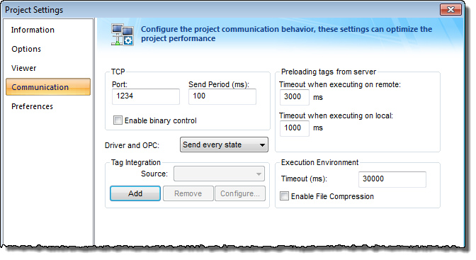
- On the Project tab of the ribbon, in the Settings group, click Communication. The Project Settings dialog is displayed, with the Communication tab selected.
- In the Tag Integration area, click Add. The Tag Integration Source dialog box is displayed.
- In the Type list, click Integrated.
- In the Provider list, click Allen-Bradley PLC5, SLC500.
- In the Name box, type an appropriate name for this tag integration source. Note that the name will be used as a prefix on names of the integrated tags.
- Click Add. The ABTCP Provider dialog box is displayed.
- In the PLC IP Address box, type the network address of the Allen-Bradley device. By default, port 2222 is assumed. If the device uses another port, then include it in the address.
- In the PLC Family list, click the device family.
Option Description PLC2 Allen-Bradley PLC-2 Control System PLC5 Allen-Bradley PLC-5 Control System PLC5 as SoftPLC SoftPLC running a converted PLC-5 system SLC500 Allen-Bradley SLC-500 Control System - Check the default memory areas. (The defaults are the same for all device families.) If you need to add another memory area to match how you have configured your device, then do the following:
- Click Add. The Memory Area dialog box is displayed.
- In the Type list, click the memory address type.
- In the Slot Number / File Number box, type the number of the slot (for O, I, S) or file (for B, N, T, C, R, F, ST).
Note: If the family is PLC2 or PLC5 and the type is O, I, or S, then the slot number is automatically 0.
- In the Size box, type the size (in bits) of the memory area.
- Click OK to close the Memory Area dialog box, and then repeat the previous step as needed.
- Click OK to finish the configuration and add the source.
If the source is added successfully, then the Allen-Bradley PLC tags will be immediately available in the Object Finder. For more information, see Use the Object Finder to select integrated tags.


