Examples of Client/Server Architecture
This section describes some example architectures applied for web-based solutions and provides information on how to configure the project for each architecture. This section does not describe all possible architectures, but it provides the concepts necessary to design and configure different scenarios based on the basic architectures illustrated below


| Setting | Description |
|---|---|
| Data Server IP Address |
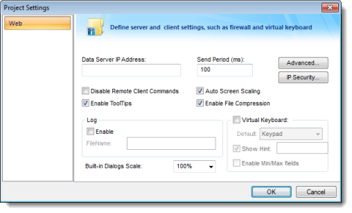
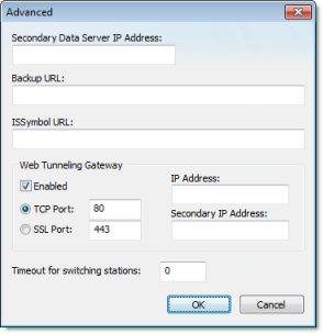
When the Web Tunneling Gateway is disabled: The Thin Client Control (ISSymbol) uses the Data Server IP Address to connect to the IWS TCP/IP Server Task. When the Web Tunneling Gateway is enabled: The Web Tunneling Gateway uses the Data Server IP Address to connect to the IWS TCP/IP Server Task. |
| Secondary Data Server IP Address | Same as the Data Server IP Address. However, the Secondary IP Address is used only when the connection with the Data Server IP Address fails. |
| Web Tunneling Gateway IP Address | The Thin Client Control (ISSymbol) uses the Web Tunneling Gateway IP Address to connect to the Web Tunneling Gateway. |
| Web Tunneling Gateway Secondary IP Address | Same as the Web Tunneling Gateway IP Address. However, the Web Tunneling Gateway Secondary IP Address is used only when the connection with the Web Tunneling Gateway IP Address fails. |
- When the Thin Clients can connect to either one of two redundant Servers (Web or Data); or
- When the Thin Clients can connect to the Server through the Intranet (LAN – Local Area Network) or through the Internet (WAN – Wide Area Network). In this case, the Primary addresses should be configured based on the network used more often by the Thin Clients. In the following examples, the LAN addresses are used as Primary and the WAN addresses are used as Secondary.
| Term | Description |
|---|---|
| LAN | Local Area Network (for example, Intranet) |
| WAN | Wide Area Network (for example, Internet) |
| Server |
Station where the following components are running:
Although IWS does not need to run in the same station where the other components are running, the following examples assume that it is. |
| Thin Client LAN | Thin Client station (Web Browser + ISSymbol control) that connects the Server via the LAN. |
| Thin Client WAN | Thin Client station (Web Browser + ISSymbol control) that connects the Server via the WAN. |
| IP_SERVER_LAN | IP Address of the Server on the LAN. |
| IP_SERVER_WAN | IP Address of the Server on the WAN. |
| IP_ROUTER_LAN | IP Address of the Router on the LAN. |
| IP_ ROUTER_WAN | IP Address of the Router on the WAN. |
| ScreenName | Name of the project screen, saved as HTML, that is open on the Thin Client station. |
Example 1: Web Server and Thin Client in the same Intranet (LAN)

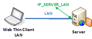
This is the very common architecture, as well as the simplest to configure. In this architecture, both the Web Server (e.g., Microsoft IIS) and the Data Server (i.e., the IWS TCP/IP Server module) are running on the same PC. The Thin Client connects to the Web Server to download the HTML screen file(s). Then it connects to the Data Server to exchange data with the IWS runtime project. Since both the Thin Client and the Server station are connected to the same network, the Thin Client can access the Server station directly through its IP address (or host name).
| Setting | WTG Enabled | Web Gateway Disabled |
|---|---|---|
| Data Server IP Address | IP_SERVER_LAN | IP_SERVER_LAN |
| Secondary Data Server IP Address | - | - |
| Web Tunneling Gateway IP Address | IP_SERVER_LAN | - |
| Web Tunneling Gateway Secondary IP Address | - | - |
- URL From Thin Client LAN: http://IP_SERVER_LAN/ScreenName.html
- Home directory of the web server (HTTP server) on the server station: Web sub-folder of the project
Example 2: Web Server with Intranet (LAN) and Internet (WAN) Connections

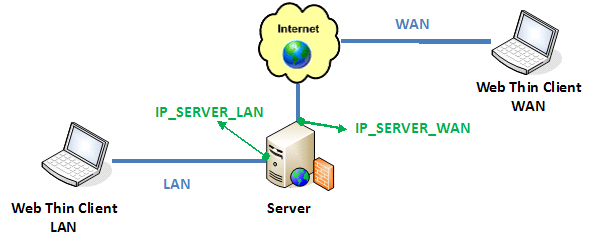
This architecture has both the Web Server (e.g., Microsoft IIS) and the Data Server (i.e., the IWS TCP/IP Server module) running on the same PC. Thin Clients can connect to the Server through either an Intranet (LAN) connection to the Server or an Internet (WAN) connection to the Server (e.g., two different Ethernet ports).
| Setting | Web Gateway Enabled | Web Gateway Disabled |
|---|---|---|
| Data Server IP Address | IP_SERVER_LAN | IP_SERVER_LAN |
| Secondary Data Server IP Address | IP_SERVER_LAN | IP_SERVER_WAN |
| Web Tunneling Gateway IP Address | IP_SERVER_LAN | - |
| Web Tunneling Gateway Secondary IP Address | IP_SERVER_WAN | - |
- URL From Thin Client LAN: http://IP_SERVER_LAN/ScreenName.html
- URL From Thin Client WAN: http://IP_SERVER_WAN/ScreenName.html
- Home directory of the Web Server (HTTP server) on the Server station: Web sub-folder of your project folder
- You must assign a Fixed IP address to the Web Server on the Internet (WAN), and the project must be running in this Server. Consult your ISP provider or IT department for further information about how to get a Fixed IP address for your Server.
Example 3: Web Server with Intranet (LAN) and Router Internet (WAN) Connections

This architecture has both the Web Server (e.g., Microsoft IIS) and the Data Server (i.e., the IWS TCP/IP Server module) running in the same PC. Thin Clients can connect to the Server through either an Intranet (LAN) connection or an Internet (WAN) connection. There is a Router between the Intranet (LAN) and the Internet (WAN).
| Setting | Web Gateway Enabled | Web Gateway Disabled |
|---|---|---|
| Data Server IP Address | IP_SERVER_LAN | IP_SERVER_LAN |
| Secondary Data Server IP Address | IP_SERVER_LAN | IP_ROUTER_WAN |
| Web Tunneling Gateway IP Address | IP_SERVER_LAN | - |
| Web Tunneling Gateway Secondary IP Address | IP_ROUTER_WAN | - |
- URL From Thin Client LAN: http://IP_SERVER_LAN/ScreenName.html
- URL From Thin Client WAN: http://IP_ROUTERR_WAN/ScreenName.html
- The Router must be configured to forward the TCP Port(s) from its public IP (IP_ROUTER_WAN) to the Server private IP (IP_SERVER_LAN).
If the Web Gateway is enabled, only the HTTP Port (80, by default) or the HTTPS Port (SSL Port 443, by default) must be forwarded from IP_ROUTER_WAN to the IP_SERVER_LAN.
If the Web Gateway is disabled, both the HTTP Port (80, by default) and the Studio TCP/IP Server Port (1234, by default) must be forwarded from IP_ROUTER_WAN to the IP_SERVER_LAN. Consult the Router documentation for further information about how to configure Port Forwarding on it.
- Home directory of the Web Server (HTTP server) on the Server station: Web sub-folder of your project folder
- You must assign a Fixed IP address to the Router on the Internet (WAN), and the project must be running in this Server. Consult your ISP provider or IT department for further information about how to get a Fixed IP address for your Server.